.png)


Ubiquiti LTU-Rocket 5 GHz PtMP LTU BaseStation Radio


Overview
Ubiquiti introduces the LTU Rocket®, the first Point-to-Multi-Point (PtMP) BaseStation radio in our LTU™ product family. Operating in the 5 GHz frequency band, the LTU Rocket is a spectrally efficient, noise-resilient PtMP AP specifically designed for wireless ISPs (WISPs).
Primary features of the LTU Rocket include:
• 600+ Mbps PtMP performance1
• Up to 64 client connections per AP2
• 2+ Million pps
• Proprietary RF filtering
1 1+ Gbps with future firmware upgrade.
2 255 client connections with future firmware upgrade.
Superior Performance
LTU is a new, proprietary technology with custom silicon and radio design that break through the limitations of 802.11 Wi-Fi technology. This enables LTU to deliver far superior performance over previous airMAX products that are based on 802.11 Wi-Fi.
The LTU Rocket is designed for WISPs from the ground floor up. Its core communications processing engine enables low latency, long-range capability, DFS flexibility, higher constellations, better power output, and improved receive sensitivity.
Seamless Compatibility
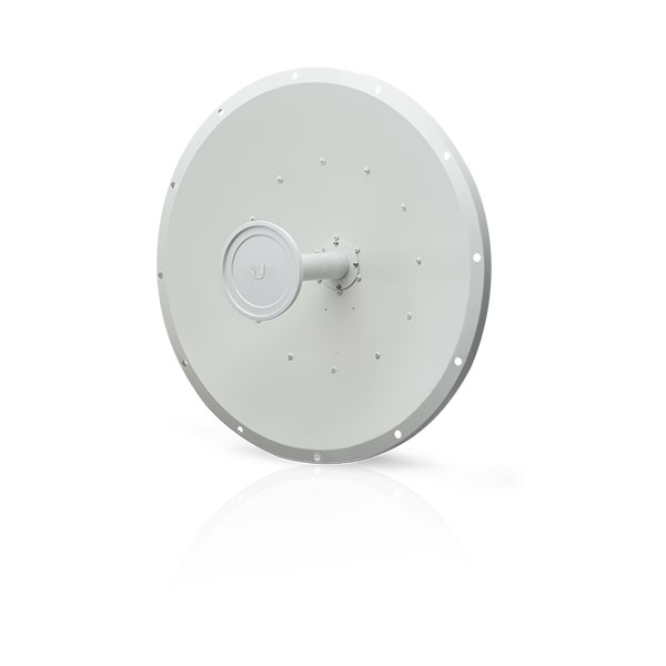
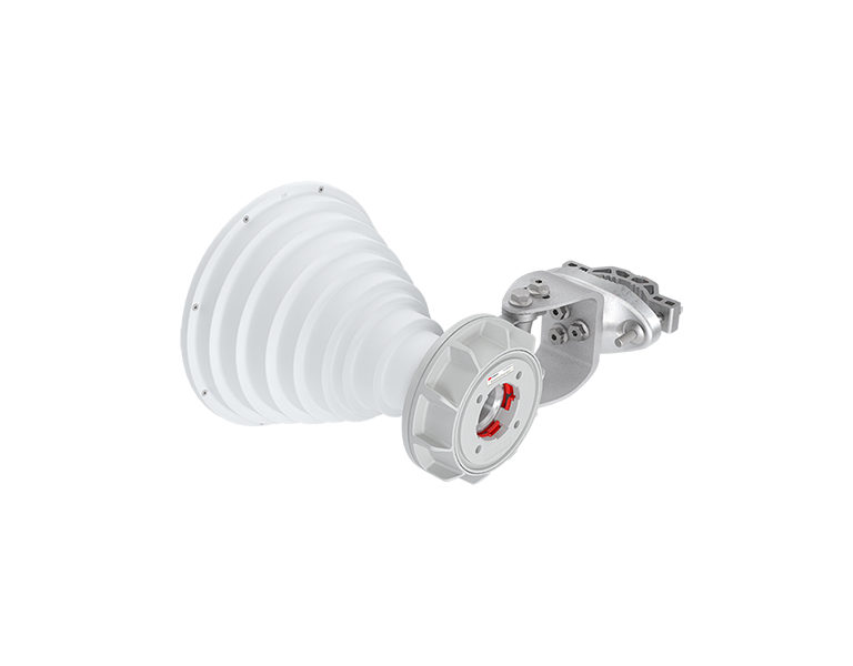
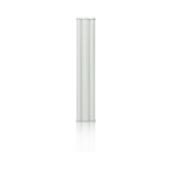
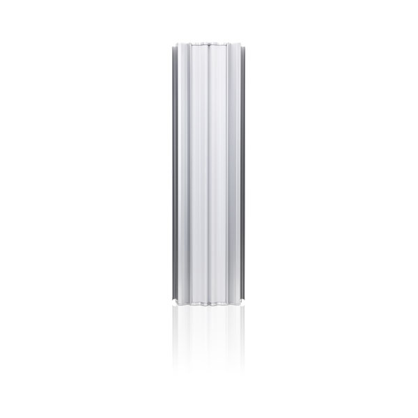
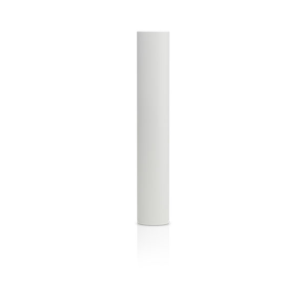
The LTU Rocket is designed to be paired with a variety of Ubiquiti antennas to suit the needs of each installation. The radio includes a mounting bracket that allows it to be used with a 5 GHz airMAX® Sector antenna or airMAX Omni antenna for a complete 5 GHz PtMP BaseStation. You can even pair three LTU Rocket radios with the airPrism® 5 GHz 3x30° HD Sector Antenna for co-location deployments.
The LTU Rocket also works with any CPE device in the LTU family, such as the LTU-Pro.
Channel Width Flexibility
Channel width flexibility allows independent TX and RX channel frequency configurations anywhere within the radio band to avoid local interference. Channel width options include the following:
• 10 MHz
• 20 MHz
• 30 Mhz
• 40 MHz
• 50 MHz
• Up to 100 MHz*
Auto Power Adjustments
By default, the Auto Output Power* option allows the LTU Rocket to set the output power (EIRP) to the appropriate level.
Frequency Split
The LTU Rocket can use different frequencies for TX and RX to avoid interference.
Signal Control
The LTU Rocket's target TX output power controls each station's TX output power. A PtMP network can manage signal levels to enhance network stability and achieve optimal wireless performance with the highest possible modulation.
Convenient Configuration
To manage the LTU Rocket, you have two options: the LTU Configuration Interface and Ubiquiti Network Management System (UNMS™). Either option lets you manually configure the LTU Rocket.
The LTU Rocket can also be used to automatically configure the stations. On each station, use the Find My AP feature to scan for APs using the same channel bandwidth, select the appropriate LTU Rocket, and then use it to configure the station.
Integrated GPS
Built-in GPS improves synchronization and allows map and Fresnel views on the Dashboard.
* Available with future firmware upgrade.
LTU Configuration Interface
PtMP Dashboard
The Dashboard offers map and Fresnel views* so you can visualize the network. The map view shows your PtMP links overlaid on a geographic map, while the Fresnel view shows the link calculated for your selected CPE, including line of sight, first Fresnel zone, and 60% clearance zone.
New graphs provide instant status updates and help you to detect connectivity issues and their effects on PtMP performance:
• The airtime distribution bar graph displays in real time how much airtime each CPE is using. Click any point to view the airtime and link score for a specific CPE.
• The AP RF environment bar graph shows ambient RF noise levels across the frequency spectrum.
• The combined remote RF environment bar graph also shows ambient RF noise levels but for the combined environment of all of the remote CPEs.
• The local and remote RX rate histograms show the receive modulation rates of the various CPEs.
Real-Time Spectral Analysis
airView® spectral analysis runs on a dedicated and independent receiver, which has excellent EVM (Error Vector Magnitude) performance.
The receiver can also perform other tasks, such as a search for channel occupancy, DFS detection, and automatic channel/ frequency assignment. Calibration (signal level measurement accuracy) and resolution bandwidth options are enhanced. Spectral zoom (user-defined scan limits) is also available.
| Specifications | |
| Dimensions | 244 x 82 x 48 mm |
| Weight | 0.468 kg |
| Enclosure | Diecast Aluminum and Polycarbonate |
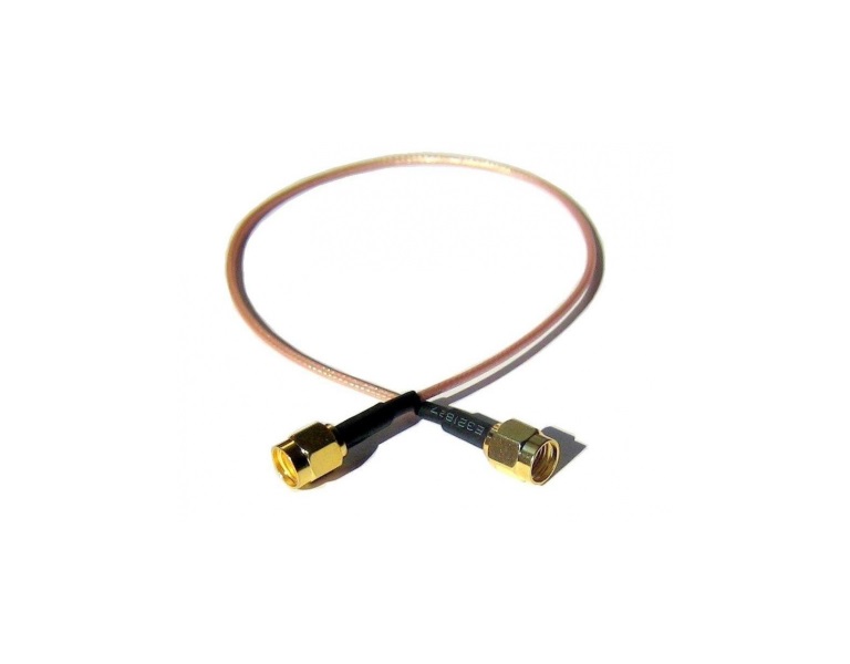
| RF Connectors | (2) RP-SMA Weatherproof (CH0, CH1) (1) SMA Weatherproof (GPS) |
| GPS Antenna | External Magnetic Base |
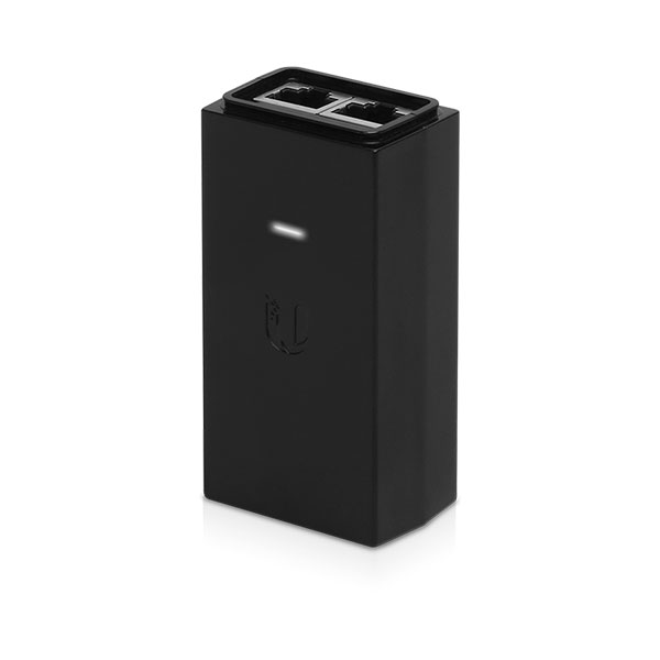
| Power Supply | 24V, 1A Gigabit PoE Adapter (Included) |
| Power Method | Proprietary 4-Pair Passive PoE Pins 1, 2; 4, 5+ and Pins 3, 6; 7, 8- |
| Max. Power Consumption | 25W |
| Voltage Range | +18 to +54VDC1 1 Full range depends on Ethernet cable length |
| Networking Interface | (1) 10/100/1000 Ethernet Port |
| Mounting | Integrated Pole Mount (Included) Rocket Mount Compatible GPS Pole Mount (Included) |
| Operating Temperature | -40 to 55° C |
| Weatherproofing | IP672 2 After installation of IP67 upgrade kit (included). |
| Certifications | FCC Part 15.407 CE EN 302502 v1.2.1, EN 301 893 v1.7.1 |
| System | |
| Maximum Throughput | 675.84 Mbps3,4 3 Values may vary depending on the environmental conditions. 4 1+ Gbps with future firmware upgrade |
| Maximum Range | 100+ km3 3 Values may vary depending on the environmental conditions. |
| Packets per Second | 2+ Million |
| Encryption | WPA2-PSK (AES) |
| Forward Error Correction | LDPC |
| Uplink/Downlink Ratio | 25/75, 33/67, 50/50 |
| OS | airOS LTU |
| Wireless Modes | AP |
| Radio | |
| Max. Conducted TX Power | 29 dBm (Dependent on Regulatory Region) |
| Frequency Accuracy | < 2 ppm |
| Channel Bandwidth | 10/20/30/40/50 MHz Selectable Programmable Uplink and Downlink Duty Cycles |


Caution! According to current Greek Legislation, of N.F.B.A.R. and the provisions of the P.D. 98/2017 the lawful use of this product in the frequency band 5150 – 5250MHz and 5250 – 5350MHz, provides for a maximum transmit power of 200 mW e.i.r.p. and in the frequency band 5470 – 5725MHz, provides for a maximum transmit power of 1 W e.i.r.p.
At this maximum power the output power of the transmitter and the gain of the antenna are both taken into account. Responsible for spectrum surveillance is H.T.P.C.
This product is CE marked, P.D. 98/2017
This product is intended for outdoor use.